Engineering a Solution: Why I Built a Drone for Zimbabwe’s Roads (Part 1/3)
Introduction
It started with a simple, frustrating reality: driving in Bulawayo, Zimbabwe, often felt like navigating a minefield. A hidden pothole doesn’t just ruin a tire; it disrupts supply chains and endangers lives. The local City Council faced a massive challenge—they couldn’t fix what they couldn’t find. Manual road inspections were slow and expensive. I realized that to solve this at scale, we needed an aerial perspective. But off-the-shelf drones weren’t built for the rugged, custom sensor work I had in mind.
In this first part of my three-part series, I will break down the mechanical engineering behind the project. You’ll learn why I chose to machine a custom chassis from aluminum rather than using carbon fiber, and how I utilized CAD to design a platform stable enough for computer vision.
The Design Philosophy: Rigidity is King
When building a drone intended for computer vision, vibration is the enemy.
Technical Components & BOM
Building a custom drone in Zimbabwe required a mix of high-end flight electronics and local rapid prototyping. Here’s a look at the core components laid out before assembly.
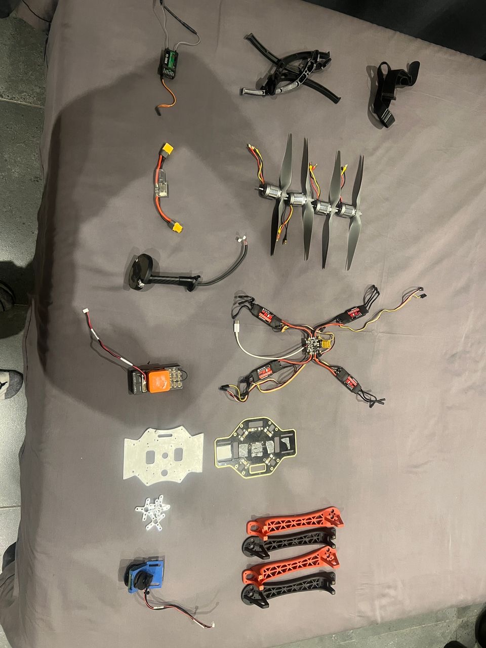 The complete Bill of Materials (BOM) for the pothole detection drone, including the Cube Orange, Raspberry Pi 5, and custom frame components.
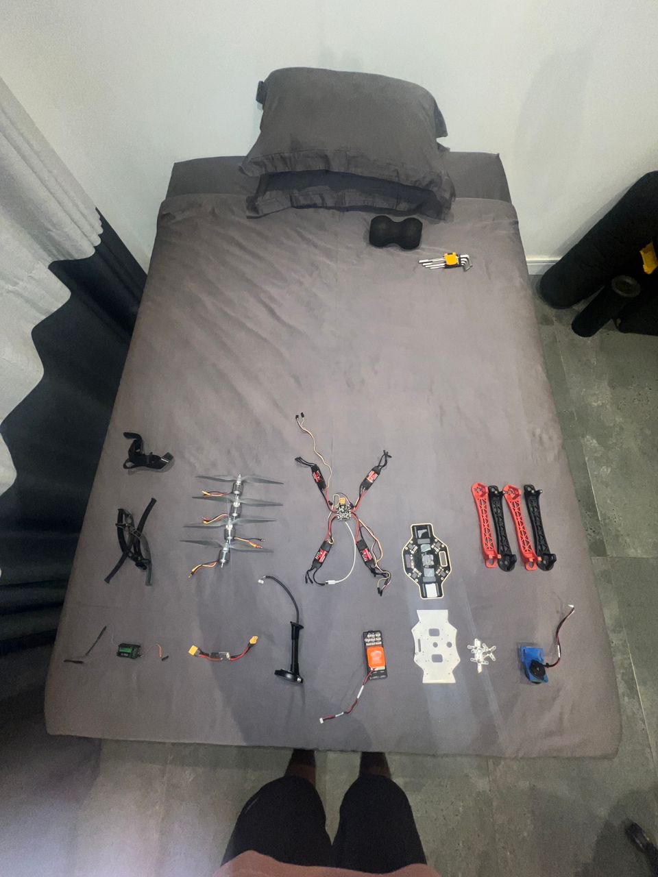 Organizing the electronics: ESCs, flight controller, and power distribution board ready for integration.
The Material Choice: CNC Aluminum vs. Plastic
Most hobbyist drones use plastic or carbon fiber frames. For this project, I took a different route.
The Constraint: Being in Zimbabwe I lacked the convenience of Amazon, so with the help of “runners” who brought down the limited drone parts available in South Africa, I eventually got access to a CMU F450 Drone Chassis that was made of Nylon so it could withstand the vibration. This was the base of the drone, where I eventually used my janky Ender 3 to 3D print attachments.
The Solution: The originally build plate did not have the rigidity to allow the plethora of sensors on the Cube Orange to function to full capacity, other than that the addition of more parts meant that a new plate was necessary. I managed to design a plate in Fusion 360 and beg a local CNC enthusiast to print this small plate.
Rapid Prototyping with 3D Printing
Throughout this process I saw to expand my skills of CAD and rapid prototyping, in which through thousands of failed prints, clogged extruders and uneven build plates I managed to develop a few iterations of the drone frame.
 The final iteration of the drone frame on display at ZITF. This build features the custom CNC aluminum build plate for rigidity and 3D printed components for sensor mounting and vibration dampening.
Mechanical Challenges
Vibration Dampening
Mounting the Raspberry Pi was a problem in and of itself. Fitting both the RPI and the Cube Orange presented an interesting design choice, where I spent way too much time with a pair of calipers than I would like to say. The Raspberry Pi and Cube Orange both needed to have vibration damping for optimal flight. Using rubber inserts to reduce the damping effect, this solved the calibration issues faced by the accelerometer and gyrometer.
Conclusion
I love the design of the drone, and despite me not documenting it to the best of my abilities, I think this is something really interesting. In the future, of course, I would transition to a smaller frame, and improve the overall print quality.
Next Up: A stable drone is just a flying brick until you give it a brain. In Part 2, I’ll explain how I integrated the Raspberry Pi with the Flight Controller to make the system autonomous.